by 3PB Team
Share

Short version: When an RF absorber datasheet shows -20 dB reflectivity centered at 6 GHz, what does that mean, how was it measured, and how do you know it will actually solve your problem? This guide walks through how absorber performance is defined, how it is measured and verified at the manufacturer, and how to validate it in your own hardware. Keep reading to learn more.
Need extra help? Contact our engineering team for a rapid response.
Step 1: It Starts With a Measurement
You have energy showing up where it should not. Maybe it is a radiated emissions failure at a specific frequency, a cavity resonance that only appeared after you installed a shield, or interference degrading antenna performance. Whatever the application, the problem is the same: a dB value at a frequency or across a band that needs to come down.
Decibels are a power ratio, not an absolute level. Every 10 dB step is a factor of 10 in power: -10 dB is one-tenth the power, -20 dB is one-hundredth, -30 dB is one-thousandth. Between those round numbers, -3 dB is half the power and -6 dB is a quarter.
| Stated value | Attenuation | Plain-language meaning |
|---|---|---|
| -3 dB | 50.0% | Half the power |
| -5 dB | 68.4% | About two-thirds removed |
| -10 dB | 90.0% | One order of magnitude down |
| -15 dB | 96.8% | Most of it gone |
| -20 dB | 99.0% | Two orders of magnitude down |
| -30 dB | 99.9% | Effectively eliminated |
We plot both reflectivity and insertion loss as negative dB, so more negative always means more energy removed. One note worth flagging early: if an emissions spike appeared after you added a shield, you are likely dealing with resonance from the enclosure itself, not radiation from the circuit. An absorber inside the shield is the correct fix.
Step 2: RF Absorber Material Properties, Permittivity and Permeability
Two material parameters determine how an RF absorber performs: complex permittivity (ε*) and complex permeability (μ*). Permittivity describes how the material interacts with the electric component of an RF wave; permeability describes the magnetic component. Both are complex numbers, written as ε* = ε′ − jε″ and μ* = μ′ − jμ″. The real parts (ε′ and μ′) represent energy storage; the imaginary parts (ε″ and μ″) represent loss. Carbon-loaded foam absorbers are dielectric materials: the attenuation comes from ε″. Carbonyl-iron-loaded absorbers are magnetic: the attenuation comes from μ″. The loss tangent, tan δ = ε″/ε′ or μ″/μ′, is a single frequency-dependent number expressing how lossy the material is relative to what it stores.
These parameters are measured with a VNA. The instrument sweeps across frequency and captures S11 (reflection) and S21 (transmission), both magnitude and phase. The Nicolson-Ross-Weir (NRW) method inverts those S-parameters to extract ε* and μ* at each frequency point. For magnetic absorber materials, the standard fixture is a toroidal sample machined to fit a coaxial airline, which gives clean extraction across a broad band. For flat samples at higher frequencies, a focused-beam free-space setup with spot-focusing lens antennas handles the measurement without the machining requirement. One practical caveat with NRW: the extraction becomes unstable at sample thicknesses near a half wavelength, so fixture geometry is selected to keep the target band clear of that condition.
This is the data you load into HFSS, CST, or any EM simulator to model how a given material and thickness will perform in your geometry before a sample is cut. We provide simulation-ready permittivity and permeability for most products on request. These curves are specific to each formulation, so we send them directly to engineers working on a design rather than posting them publicly.
Step 3: Designing the Solution, Narrowband or Broadband
Once the target frequency, required attenuation, and physical constraints are defined, the solution falls into one of two categories.
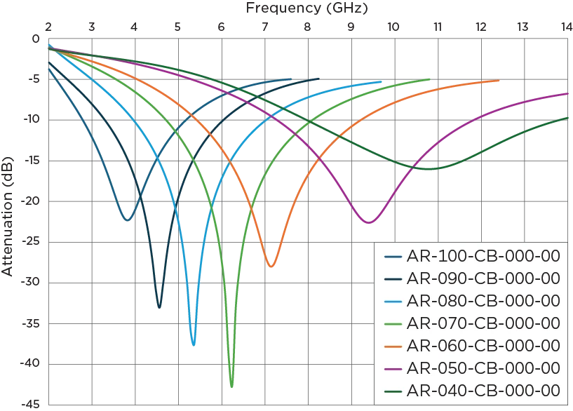
A magnetically loaded sheet is a resonant absorber tuned to a specific frequency. The sheet thickness and magnetic permeability are chosen so that the reflection off the front face and the reflection off the metal backing arrive at the surface 180 degrees out of phase and cancel. That cancellation produces the deep, narrow null you see in arch data. It is the right choice when the threat is at a known frequency or a narrow band. Broadband carbon-loaded foam works differently: energy enters the material with minimal front-surface reflection and is attenuated by resistive loss as it travels through. The result is a smooth, wideband insertion loss curve rather than a sharp null. Use it when the threat covers a wide band or when the exact problem frequencies are not tightly defined. Parts are available as flat sheets, precision die-cut pieces, or as dispensable absorbers that are applied directly into a cavity or enclosure and cure in place. Our frequency selection guide can help match the right material to your application.
Step 4: Internal Verification, the Arch and the Tunnel
Modeling tells us what should happen. Before parts ship, we measure the fabricated sample to confirm it does.
Flat magnetically loaded sheets are characterized on an NRL arch. The sample sits on a metal ground plane, and transmit and receive horns mounted on a semicircular arch illuminate it at a controlled near-normal angle. We sweep the VNA with the bare metal plate in place as a 0 dB reference, then sweep again with the sample on the plate. The difference is the reflectivity, plotted across frequency. The depth of the null shows how well the front and back reflections cancel at the tuned frequency; the width of the null tells you the usable bandwidth.
Broadband carbon-loaded foam is characterized in a transmission tunnel. The sample sits between two facing horns; the VNA measures S21 through the empty aperture as a reference, then again with the sample in place. The reduction in transmitted power across frequency is the insertion loss. For foam and other resistive materials, insertion loss is the right figure of merit because these materials are used in transmission, not mounted against a metal backing.

Step 5: In-Situ Validation
Internal measurements confirm performance in a controlled setup. The absorber still has to work in your hardware. Once samples are in hand, validation is straightforward: run the same measurement that identified the original problem, with and without the absorber installed.
For EMC compliance: rerun the scan before and after. If the failure frequency drops below the limit, the material is doing its job. The dB difference at that frequency is your margin.
For cavity resonance: monitor a signal inside the enclosure or probe it with a near-field sensor, and compare the resonant peak amplitude and Q factor with and without the absorber installed. A correctly specified part loads the cavity and reduces both.
For antenna systems: compare patterns with and without the absorber, looking for reduced sidelobe levels, improved front-to-back ratio, and less pattern ripple from enclosure reflections. This is the same principle behind PIM mitigation panels on a cell site.
What 3PB Solutions Provides
We provide three types of test data. Complex permittivity and permeability are available on request for most products; these are the simulation-ready curves engineers use to model material behavior in their own geometry before committing to a design. NRL arch reflectivity data is available for the magnetically loaded sheet products. Transmission tunnel insertion loss data is available for the broadband foam products. Every sample kit ships with published datasheets covering the target frequency range. For qualification programs, we can supply test data measured from the specific production lot being shipped, so the numbers you receive match the parts you receive.
Getting Started
Request a free sample kit with published test data for your target frequency, or contact our engineering team to discuss material properties, modeling, or custom test data for your application.
Quick Contact: Call (855) 785-5660 or email sales@3pbsolutions.com.
Product Finder: Search by frequency, thickness, and base material to find the right part number.
Frequently Asked Questions
The decibel is a power ratio. Every 10 dB is a factor of 10: -10 dB is one-tenth of the power, -20 dB is one-hundredth, -30 dB is one-thousandth. A reflectivity of -20 dB means 99 percent of the incident energy is absorbed rather than reflected. We plot both reflectivity and insertion loss as negative dB, so a more negative value always means more attenuation.
Both are measured with a VNA. The instrument captures S11 and S21 across frequency, and the Nicolson-Ross-Weir method extracts complex permittivity and permeability from those S-parameters. For magnetic absorber materials we use a toroidal sample in a coaxial airline. For flat samples at higher frequencies we use a focused-beam free-space setup with spot-focusing lens antennas. The extraction is sensitive to sample thickness near half-wavelength multiples, so fixture geometry is matched to the target band.
The arch measures reflectivity of a metal-backed flat sheet; the tunnel measures insertion loss of a foam or resistive material in transmission. Both use a VNA to compare the sample to a reference. The arch reference is a bare metal plate; the tunnel reference is the empty aperture between the horns. Use arch data to evaluate magnetically loaded sheet absorbers. Use tunnel data to evaluate broadband foam.
The magnetic sheet is tuned to a specific frequency. The sheet thickness and permeability are chosen so that the reflection off the front face and the reflection off the metal backing arrive back at the surface out of phase and cancel. That produces the sharp null in the arch data. Broadband foam works by resistive dissipation across a wide frequency range rather than resonant cancellation at one frequency, so the attenuation curve is smooth instead of peaked.
We provide three types of test data: complex permittivity and permeability on request for most products, NRL arch reflectivity curves for the magnetically loaded sheet products, and transmission tunnel insertion loss curves for the broadband foam products. Sample kits include published datasheets for the target frequency range. For qualification programs we can supply data from the production lot being shipped. Contact us to discuss your requirements.